Klauskorrektor I: First phono stage
This is the first phono stage I built. Now running at a friend's system. Not bad at all... It started like this:
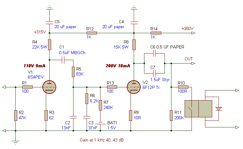
... then I changed C1 position to between RIAA network and R7-R13. Now C2, C3 are DC-biased to 110V - sounds much better.
Tubes are Soviet 6C4P (6C3P will be just as good) and triode part of 6F12P (unique high mu - high Gm combination). I like this combination, although output impedance is very high (over 5kOhms). DO NOT copy RIAA network values - these are not standard. Some where changed in the process, some reflect my own idiosyncrasies. Batteries (AAA size alkaline) are soldered (don't use cheap battery holders!). Photo below is from klauskorrektor II, the first is similar. Over one-and-a-half year in circuit, batteries lost about 50mV. If space is limited, smaller alkalines (types N, LR1 et al) are just as good. Soldering alkalines is easy, they don't die from heat as quick as lithium cells.
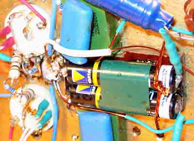
Apart from power supply lines, there is no wiring as is - all wiring is using components' own leads. For a star ground, I use a small (1-2 sq.cm) copper piece, soldering all grounded parts to it first (including batteries) - looks like a pregnant spider. Then the spider is bolted to the chassis between input tubes, and the opposite leads are soldered in place.
I placed everything into a 320*320*120mm aluminum case, split into three screened compartments: Iron+Rectifier, Regulator, Audio. Heater regulator is described here http://www.klausmobile.narod.ru/appnotes/an_11_fetreg_e.htm.
Plate supply is based on Hexfred rectification - Choke Input. A small cap (0-4uF) before choke adjusts output voltage, it doesn't change overall inductive filter behavior.
(schematic below was changed - see following notes).
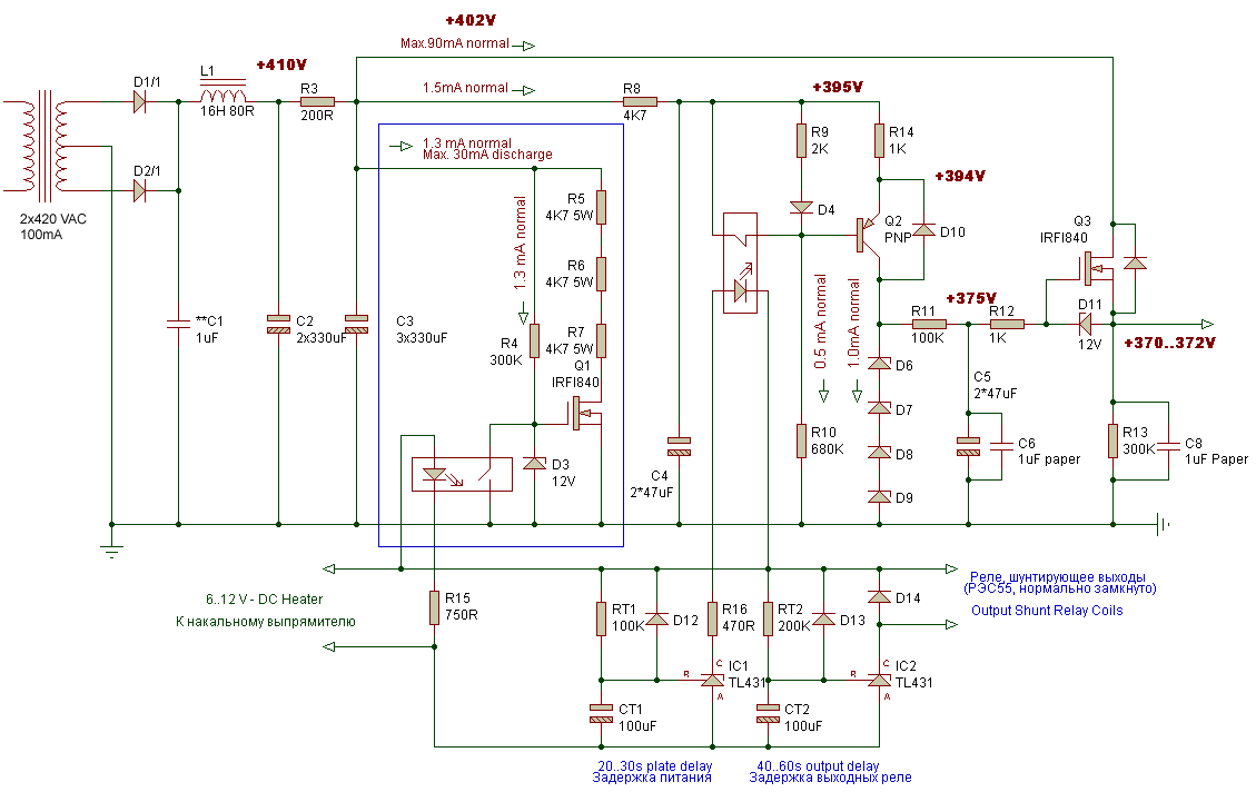
Time relay (CT1-IC1) disables regulator output for about 1 minute. Note that the two optocouples (FET 400V/50mA output relays) are different - the one on the right is normally shorted. At power-off, CT1 quickly discharges through filaments, and discharge circuit (blue box across Q1) starts conducting as long as there's energy in C2, C3.
To prevent overvoltage across C2, C3 when the time relay is OFF, connect first optocouple's LED to the time relay. Now, Q1 will be open from power-on until the regulator kicks in.
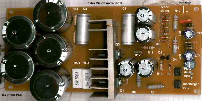
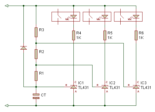
Eventually, I changed delay logic, so now the relay uses separate timings for discharge and regulator enable. Here's a sketch of a triple-delay timer using a single timing cap
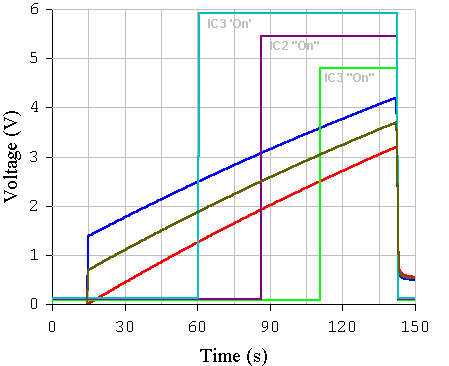
Calculating R/C values is simple with a plain paper chart like this (total R should be under 200K):
Credit and references
Index in Russian - Index in English - Mail