WARNING ! HIGH VOLTAGE CIRCUIT. USE AT YOUR OWN RISK
Measurements Basics
The tester is an entirely analog device controlled by a PCI bus industrial DAC/ADC card. As built, it enabling curve-tracing of small single and dual triodes with indirect heating. Dual triodes can be tested each side separately or both sides in parallel. Full tests of pentodes are possible with an external screen grid supply. The design is easily scalable for power tubes (as for Ua/Ia limits), although to drop grid bias below -15V (opamp limits) you need to add a special DC amplifier with it's own power supply. Once a set of tube curves is retrieved, the software can estimate operating point, linearity, Gm-mu-Rp curves, etc.
Static test specifications
Dynamic test specifications
A/D resolution, quality components, proper calibration procedure set the systems' dynamic range. A commercial tube tracer by Audiomatica (Italy) uses 16 bit A/D and D/A conversion (unipolar, I presume - it's 5 bits, 32 times better than my 12-bit bipolar setup). This enables precise current measurements over a 1:1000 operating current range - 12AX7 to 6C33C, with 700V plate/screen and -150V control grid scale.
My dynamic range is less demanding, besides - I don't have precise calibration tools so 11 bit precision is OK, anyway, the errors of setting levels with a DMM are worse than ADC resolution. Audiomatica has all A/D functions custom-built inside the tester case, this reduces DC errors and ground noise. Another design with microprocessor and A/D functions on board was published by Federico Paoletti - it is complicated indeed, he also uses 12-bit A/D, but in SE mode, one bit better than mine.
Plate current sensing. A plain amperemeter can be plugged in either cathode or anode path, but with ADC - all voltage test points must be within 5V from ground. That is, Ia sense resistor can not be plugged into plate (high potential) network - only under the cathode.
Ua supply and Ia sense network are built over a voltage-controlled 300V/50mA shunt regulator (or call it an SE amp which it is indeed). Shunt layout is immune to self-destruction (even if all active parts fail, there's still Rseries in curent path); most heat waste is into a dumb resistor, not the active device. Regulating transistor's source and gate are within 5 volts from ground, and can be controlled by an opamp with ground-referenced power rails.
Since the plate supply floats, all current that flows out of P.S. into Rseries and then into plate must return to P.S. through Rsense (that's the only path in circuit). Voltage drop across Rsense is proportional to Ia, not Ic as it may look. Plate-Grid current - if any - is taken from the same plate supply, and also returns there through Rsense (see a picture in the 'Grid' section). Leakage path Rleak provides minimum regulator current (otherwise it's unstable) and does not affect Usense readings. Don't be scared to use a floating 300V source. It is safely anchored to ground with a low resistance path (Rsense << P.S. impedance).
Shunt layout has one disadvantage - available current decreases as Ua increases, but considering the Ia<Pa/Ua safety requirement, this decrease is quite practical. With the parts I used ( 22W transformer), the Ua/Ia envelope is as shown. The design is easily scalable up, to raise the envelope just upgrade power supply, T1 heatsink, Rseries and Rsense. You'd need to recalculate Rseries, Rsense anyway, unless your transformers are identical to what I used. Even if you're not going after power tube tests, it's worth using a 400V P.S. to have decent current margin above 200V. High/Low settings on the graph refer to two sets of Rseries, Rsense used. Within each, it is possible to magnify current scale using D/A card's programmable gain amplifier (at the cost of higher noise).
Grid current sensing is a quite crude setup - sense resistor Rgs inserted between opamp output and feedback tap. Rgs senses Ig = - Iag (Plate-Grid) + Igc (Grid-Cathode). Forward current - Igc - occurs at Ug close to or above 0V and at high Ug is comparable to Ia. Reverse current - Iag - is a Ua-dependent mix of leaks. Iag is THE grid leakage current in normal, negative-bias, operation, and for small triodes must be less than 1 uA (5-20uA for power tubes). At some small negative bias point, depending on Ua, Iag equals Igc, and resulting Ig=0. As you can see, floating supply guarantees that Igc component does not affect voltage drop across Rsense.
Ugd, Ug buffers are scaled to read equal voltage values when Ig=0 (for -10V max Ug, set 5V at each buffer output). Difference between buffered Ug, Ugd indicates Ig condition that is calculated by sotware. As built Ig range is 1..200 uA; 1uA translates to about 10mV, or 4 ADC counts. At greater Ig, the opamp is unable to set Ug as ordered, and the difference between Ug set by DAC and returned to ADC (or an ADC overflow) indicates this condition. In practice - with resistor values as shown - the grid amp chokes at Ug=+0.5..+2.0V. Negative Ug goes down to -10V, but with a 20V powered opamp can be extended to -15V without an additional gain stage. Going lower requires a discrete Ug amplifier.
Note that with significant grid currents, voltage drop on 1 kOhm grid safety resistor is distorting Ug monitor readings, but actual grid potential can be reconstructed with software. Anyway, tubes are not supposed to operate with too high Ig.
Loops and Leaks. Current through Rsense is always a fraction above actual Ia - the additional error current is caused by R2-R1 divider which pulls part of plate supply current into the Uxa source then to ground. This current must return to plate supply, the only return path is through Rsense. It equals Ierr=Ua/R2 and caused Rsense error voltage, Uerr=Ua*Rsense/R2. Obviously, R2>>Rsense, so Uerr is not too great and is easily accounted for. There is another plate-ground divider (Ua monitor network) on the actual board, which adds a same sort of error. These error voltages across Usense are independent of Ia, so to log them (for each Rsense resistor) simply remove the tube from socket (Ia=0), sweep Uxa from 0 to max, and log Uerr=Usense(Ua). This also adjusts for any residual zero offset. Do it for each programmable gain setting.
There are also leaks through FET gate protection resistor and zeners but these are insignificant when FET's gate voltage is in linear area (2-4V above ground). You cannot substitute MOS T1 for a bipolar - functionally, they work fine, but base current flowing into Rsense is too volatile to account for correctly.
D/A interfacing. If you decide to copy this design, make a good search on available D/A card options. You'd need a card with 2 DACs (these are usually independent in a 2-channel chip or two separate chips) and 6 differential ADC channels. 12 bit resolution for D/A and A/D is enough. Low-cost boards (unfortunately, 'low' means under 1000 USD) always have a single ADC with an input multiplexer, and usually have a programmable-gain amplifier (gains of 1,2,4 or more). The good side of it is, all inputs are identical (same offset, gain, scale, linearity). The bad side is, ADC input is a switching pig. Take special care about interfacing source outputs to ADC inputs. When an analog switch opens, memory capacitor in sample-and-hold drags instant current from the buffer, and if the buffer's output impedance at sampling frequency and it's harmonics, not DC is high - the reading will be modulated by these current pulses. Opamps can oscillate with such load! Their impedance in megaHertz band is too high. Normally, the first ADC reading is not affected, it's the subsequent transient that matters - if it's too long, the next reading will be mushed. So, the bad news is, you can't tap to a plain R-R divider (too high impedance), you must use a fast yet precise buffer.
The board I used has the following specs (most important are analog interface SOA and impedance):
These are quite typical for an entry-level medium-speed boards in USD300-600 range. Fully optocoupled boards cost at least 50% more, they decouple analog part from some of PC's noises but have the same problems interfacing to external world. Once you have your card's specs, you must refer to the ADC chip datasheet to make a proper buffer selection. Linear Tech docs were very informative on this issue, however, the whole D/A card with multiplexers and wiring is a load far worse than a single ADC !
The dual-DAC design, unfortunately, also means you cannot test pentodes in fully PC-controlled mode - only with an external screen grid battery (pentode mode) or a plate divider (ultralinear mode). Audiomatica Sofia tester has three DAC channels so the screen grid can be driven independently.
Design and Build Notes
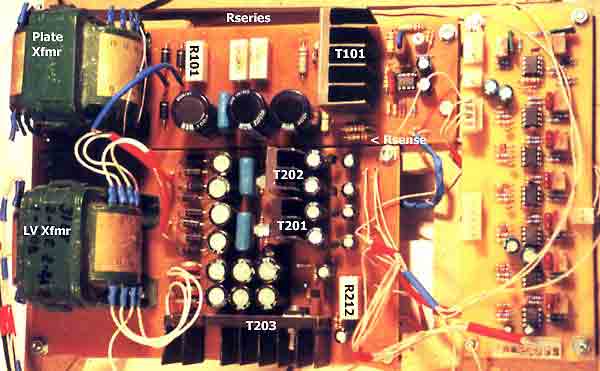
I was building the unit step by step, board by board, so there's three boards - High Voltage regulator, Low Voltage regulators (heater and opamp supply), and Opamp board (buffers). Ideally, it's worth re-designing these boards into one PCB, reducing size and KabelSalat, but it's working fine as built. LV board powers the other two, build it first. You'd need a precise voltmeter and ohmmeter (get the best, as for the ohmmeter - just take your sense resistors to nearby lab) as the only measurement tools. Oscilloscope is helpful in debugging the HV board. It might ring on leading edge, although I believe with all parts as built it is very stable. A D/A board itself is an oscilloscope - even at 100 kHz sampling rate it fits the purpose, most cards are bundled with a oscilloscope demo software.
A. LV Regulator Board

All secondaries on LV transformer are floating independently! The 2x20VAC/0.5A secondaries for opamp supply produce 30VDC, so I used 2-stage regulation. For each rail voltage: first, a zener+follower in virtual ground setup regulates to 20V, 20mV ripple - then uA78(79) 3-pin regulators have an easy task. One 7815+7915 pair for input buffers and HV board opamp, another pair for output buffers. Follower transistors are any 1A (or greater) TO-220 Darlingtons on 50 sq.cm heatsinks. Rectifier diodes (I used Soviet surplus parts so the part numbers look odd) - use fast 10A/100V for heater bridge, Shottky or plain, and fast 2A/150V for opamp bridges.
Heater regulator uses IC205 (TL431) for voltage regulation, R212 and IC206 for current limiting. Current limit Ihtr.max=2.5V/R212 (also includes feedback divider current). Uhtr buffer must be set to 50% gain, reducing typical 6V to ADC-acceptable 3V. Heater regulator transistor can be any 5A or beter N-MOS with Rds of 1 Ohm or less. The whole gate control circuitry is powered from +22V rail through R207-C217-R208, which delay heater voltage on power-up and limit Ugs to safe 0..+12V range. Uh control - R211 - is mounted outboard. Actual load regulation with IRFI540 is about 30mV per 1A current (0.030 Ohm DC impedance measured at tube socket pins).
The ground pin array on the right edge of LV board is the one and only Star Ground for the whole unit. Make sure the heater ground wire current does not mess up the readings! For tuning opamp board, use IC205 as a precise -2.5V and -5.0V reference (very stable but not absolute).
Afterthought: I added a 'Heater Overload / Short' LED on front panel - LED in series with 200 Ohms wired parallel to R212. A high intensity LED is well visible when voltage across R212 exceeds 1.2V (half of max). To indicate a true short, can insert a LED directly between IC106 cathode and T101 gate. Or a plain analog voltmeter.
Afterthought: I added a 12V/0.23A fan, hooking it up to C216 legs. It quickly discharges C216 on power-down. If you're not going to use a fan, decrease R205 to 470 Ohm / 5W - this will speed up discharge. Fan noise is an excellent indicator of heater overload.
B. HV Regulator Board

24/02/2001: Just discovered that the plate supply rings when loaded with high-Mu, high-S, high-frequency tubes like 6S3P. The circuit needs debugging, probably a decrease in compensating capacitors?
03/03/2001: Fixed most ringing by ferrite beads on all leads. However, problem persists on tubes with both very high Gm and very high Mu, 6S45P and 6F12P pentode
12/03/2001: Fixed even these babies by adding a 100kOhm grid-cathode leakage path. This, BTW, means that grid drive amplifier senses this leakage as 'grid' current - it is easily deducted in software. So far so good!
To reduce heat and improve precision, I split Rseries and Rsense into two halves each. On-board Rseries=6kOhm (R102-R104) and Rsense=150 Ohm (R116) are for measurements up to Ia=5V/150 Ohm=33mA. Outboard, identical 6kOhm and 150 Ohm shunts can be switched on to double Ia to 66 mA (which is actually above supply rating). Rseries runs very hot, even at doubled power ratings. They need not be precise or matched. Rsense MUST be precisely measured, as precise as you can. Rsense must not change with temperature or time. Use at least 1W for each half to keep them cool, and place away from Rseries, T101, rectifier and other hot parts. Rectifier diodes are fast 1kV/1A (BY255 etc.).
A forward-correction link R106-C105 stabilizes leading edge of Ua pulse - with settling times around 1ms. Use any precision, low input current opamp (IC101 - I tried OPA227, OPA228, NE5532) and any 500V, 1A minimum N-MOS hexfet (T101). There's a common misconception that a modern HexFET switch is no good in any linear application - well, here it controls quite small currents better than any bipolar can do!
Make sure high voltage board traces are at least 3mm apart from LV traces, paint them with insulating resin when ready. Put an insulating pipe over T101 drain pin. C105 must be 500V rated (mica or film). R115 trimmer on as-built schematic is not necessary - use trimmer in Ua buffer amp on the opamp board. R106-107 and R114-113 are critical - they set Uxa/Ua gains. Their absolute value is not as important as long-term and thremal stability.
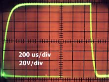
Test/Tuning: Ground Uxa input - plate voltage must be within 0..+5V. Drive +3V 100Hz pulse to Uxa input, first without load then with a 6kOhm wirewound + 1nF dummy connected with 1 meter long parallel wires to anode-cathode PCB sockets. This takes care of any load reaction. Leading edge and shelf of the pulse must settle in 1 ms, no overshoot, no shelf sagging, and look like a textbook low-pass response. In case of overshoot, increase C106 to 15nF maximum. The circuit hates capacitance (larger than a few nFs) in plate-cathode path, don't try to 'improve' it this way.
Afterthought: If both HV and LV boards are switched off simultaneously, HV caps are quickly discharged down to about 150V (that's opamp shorting T101 to cathode) then opamp power caps are discharged, T101 shuts down and HV discharge 150V to 0 takes a few minutes. To be safe, increase C107-108 to 470uF, replace R117-R118 with forward conducting 200mA diodes. Opamp will stay on long enough to discharge HV caps. Don't increase C107-108 further, otherwise the opamp will turn on too late to suppress plate voltage spike on powerup.
Afterthought: I inserted a plate voltmeter (300kOhm) parallel to Rleak (R105). In this setting, it reads Ua+Usense. A switch allows to measure voltage across C103 (filter output). In any setting, it does not offset Ua reading.
C. Opamp Board

All six ADC buffers are identical twin-opamp noninverting amplifiers with maximum gain of 2. Output zeners are required by ADC specs - it withstands -10V..+10V (PC power off, more with power on). Use unity gain stable, high precision dual opamps with low bias current or bias current cancellation network (OPA 2277, OPA2227, OPA 2234 but not OPA2228 - unstable at 1 gain). Use quality screw-driven, multi turn trimmers. Use stable, 1% resistors for all feedback dividers, R301,311, R317- these are critical.
R318 and protection diodes are a precision-vs-safety compromise. Normal reverse current of a small general-purpose diode is about 100 nA which sets a practical limit for grid current sensing, so 0.25 uA is a good measurement threshold (it's ok even for small preamp tubes) and 100 uA is a practical maximum (completely unacceptable for audio triodes). R313-R316 are set according with these values; they can be increased or decreased if a different Ig range is required, - as long as circuit noises, drifts and DAC resolution allow. Special low-leakage diodes have reverse current as low as 0.1 nA - with these, circuit will work fine at low Ig . These diodes are Philips BAS45, BAS116, BAV156, BAV170, BAV199 as well as some PiN RF diodes. My dealer doesn't stock them so I haven't tried it. Good luck! A further step will be replacing software calculations with a quality instrumentation opamp (INA110, INA114 - expensive but cheaper than NOS tubes) for better Ig sensing precison.
To test and trim the board: power up. Apply 2.5 VDC (pos or neg) to all analog inputs. Set Grid channel gain to 1:2 (Ug=5V at grid output). Set all output buffers gain to +2.5V output (2:1 reduction in Ug channel, around 2.5:1 in Ugs, all other channels 1:1), except for Uheater that must be set to 2:1 reduction. These settings will be trimmed again when the whole system is assembled.
D. Wiring together
I skipped remote controls for switching on HV regulator from the console - used series-wired manual power switches. Clean grounding is essential for small current measurements. Wiring to your D/A card is all card-specific. Just make sure that input ground from D/A card is grounded to a common star point. Advice: After your unit is assembled and tested - replace all on-board connectors with solder joints. Connectors are convenient in prototyping but they don't go well with small current and voltage measurements. To connect the tester to a PC-based card, I use a 1.5meter UTP-8 cable (standard LAN cable with 8 unshielded twisted pairs; STP cables add shielding for each pair). 2 pairs for DAC and analog ground, 6 pairs for ADCs in differential mode.
The boards with transformers take up slightly less space than an A3 sheet, 90mm high including transformers. As for the socket arrangements, there where four historic options to battle:
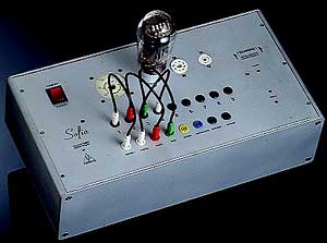 |
Audiomatica nowadays uses manually wired connections for any imaginary pinout (like a WW2 switchboard) - fits all tubes but is a safety problem. |
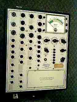 |
Some Hickok testers used a few dozen sockets, hard-wired for individual pinouts. 39 in this one! Convenient, safe but I don't have so much space, neither the patience to solder this rat's nest! |
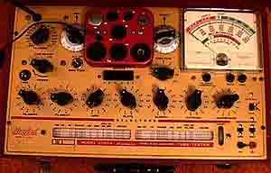 |
More Hickok types have many rotary switches connecting pins to circuit, so only one socket of each type is required. I dismissed the idea - didn't like KabelSalat around the rotaries (which I could hardly scramble into place for a start). |
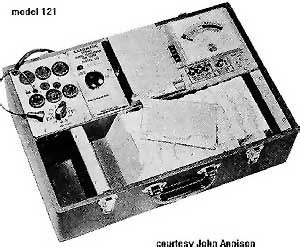 |
And another option to reduce human error was a punch card system - individual card set the wiring and voltage for each tube type. Hickok listed up to 3600 different cards! |
I used a mix of the two first options. One miniature and one octal socket are hard-wired for the most common dual triodes (ECC81/83/88, 6SN7/6SL7), with switches energizing left/right plate (grids and cathodes are paralleled). Another pair can be wired with jumpers, Audiomatica-style, using military grade switchboard plugs. For a quick left-right matching in dual triodes, I plug in mA-meters instead of a plain jumper wire, .
What about operator's safety? What happens if for any bad luck you plugged hot plate supply lead into what happens to be grid, or cathode, or heater? Well, first of all don't let it be hot when it's disconnected. The plate regulator must be shorted to Ua=0V at all times, excluding the actual measurement sequence. When it is over, the software must cycle to determine empty socket or tube-in-socket condition. The only correct tube-in-socket condition is when heater current is within 0.1A...1.5A window. If it is, wiring test can begin by gradually raising Ua (Ug=0). If the returned Ua monitor voltage doesn't match Ua set by DAC - there's a short somewhere. You won't hurt the tester by doing so (you change tube-to-source wiring only, not the sensors-to-source wiring inside tester. Sensors connected to ground remain grounded). With Ug=0, a triode will start conducting early and smoothly, and by sweeping Ua=0..50V at Ug=0 the software detects if Ia/Ua/Ug behavior is normal. These voltages and currents will not destroy the tube or sensors at any possible wiring error.
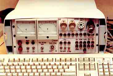
The light-grey case looks sexy, isn't it? It's a ... $5 portable file cabinet by HAN, apparently modelled upon a Viewsonic monitor. Even has sort of two handles on each side and a locking lid with a handle.
Calibration. Some ideas. Credits and References
Before you connect your unit to the PC, check it in standalone mode. Ua must be 0 with zero input, and react to -2.5VDC input by approximately 150VDC Ua voltage (you have a -2.5/-5.0V reference in heater regulator). Grid voltage = 2x Uxg, grid sense voltage at both Ug and Ugd buffer outputs - equals Uxg. Heater supply must drive 1A continuous current without choking and return Uhtr, Ihtr as set above.
Calibration itself is done with ADC/DAC connected by jumper wires (Good solid common Ground is a must). Phrases like 'Drive 2V from DAC to input X' mean setting 2V on DAC's control terminal (for an 11-bit scale spanning 5V, this means write code 032AH into DAC port). Not the 2V on the external voltmeter. 'DAC output voltage' means what's written into DAC etc. Even a 12-bit D/A card beats a 4-digit DMM in precision, so I rely on the card whenever I can do it without adding external dividers. Hopefully, my ADC and DAC 5V references are only 1-2 millivolts apart (the levels assume -5V..+5V measurement scale for DAC and ADC).
Ua - HV and monitor output (no plate-cathode load). Drive 3.3V from DAC to Uxa input. Using a quality voltmeter, 200V scale, trim gain to 198.0 VDC at plate-to-ground. Now read ADC from Ua output buffer, trimming this buffer gain until ADC reads exactly 3.3V (if both ADC and DAC have same resolution depth, their codes must match to within 1 LSB).
Grid - Ug - Ugd (no grid load). Temporarily connect ADC to Grid output. Drive -2.0V from DAC into Uxg output. Trim Grid amp until ADC reading corresponds to -4.0V. Now disconnect ADC, tap voltmeter to Grid output. Sweep DAC from -5V to 5V, at the extremes the voltmeter must show at least 10V at Grid - no opamp clipping (10V Grid = 12.5V opamp output). If your opamp clips at, say, 9V - either take it as is or reduce grid current sensing resistor. Return DAC to a fixed unclipped value below 5V, say, +4.5V or -4.5V. Hook ADC to Ug output buffer, trim it's gain until ADC readings match DAC output. Repeat the same for Ugd (Grid Drive) buffer. Sweep DAC from -5V to +5V, checking that Ug=Ugd at all intermediate points (1 LSB difference is OK).
Ic (no load) - Disconnect Ic buffer from Rsense, make a close loop (DAC -> Ic buffer -> ADC), trim Ic gain until ADC and DAC codes match.
Heater monitors - By now you should know! Anyway, these are least critical measurements and what you set with DMM before is sufficient.
Leave the unit on for a few hours, and check calibration settings again. If OK, seal the gain trimmers with epoxy paste.
Overall, long-term absolute error margin can be as low as 2% on Ua, Ig. But it's not absolute error that matters, it's the overall linearity on each axis (Ua-Ug-Ia) within one measurement cycle that matters. After all, the purpose of this design is to evaluate tube's capacity to amplify linear, low distorted signal - and then make decision about proper operating point. Whether the absolute operating current is 10.0mA or 10.2 mA doesn't really matter. Linearity depends mostly on passive components and wiring. For example, if Rsense changes with temperature, and you increase Ia slowly, then changes in Rsense power dissipation will continuously distort Ia readings (hard to find unless you log it with a precise voltmeter). As a solution, use a massive precision sense resistor with tenfold wattage rating. KNP wirewounds are OK. Or swing Ua/Ug quickly so that changes in Ia are too fast to modulate Rsense. Low-level linearity and DC offset can be badly affected by ground loops, thermocouple effects in mechanical connectors, etc.
Measurement protocol and software tweaks can cancel out some errors, but do not resort to it unless all hardware treatments were used. For example - averaging many ADC readings over 20ms interval cancels 50Hz AC hum. But why not simply shield the cables and reduce ground loops? This will kill AC hum in ALL lines, control and output, while software averaging helps the outcome but not the roots of the problem - AC hum in both Uax and Uxg control lines can cause odd readings. Not to mention that no oversampling can fix the PC's high frequency noise.
Software
As for the software... Unfortunately, my programming endeavours ended about the time DOS v5 was released ... getting back to it in Win2k era is painful. Anyway, the software is in the works, for DOS text only, so the graph data must be exported to Windows Excel for presentation. Check the Audiomatica user manual link to see what needs to be included in a good software tool. Some tips:
Use heater current sense for protection. Software continuously polls Ih ADC and when it's below 100mA (=no current), shorts Ua to zero, terminates all tests to 'Insert the tube' waiting mode. After Ih is sensed again, software delays 20 seconds until it returns to under 1A (or whatever is your tube's maximum heater current), it it does - enables tests, if not - flags 'Heater short' error.
Use grid drive sense for protection. Any time Ug or Ugd causes ADC overflow, immediately return current test to Ua=0. Any time Ug-Ugd exceeds +/-5V, return too. This is not self-destruction yet, but proceeding further is dangerous. Anyway, high Ig condition has is useless in real circuit.
Use Ua monitor for protection. Any time Ua monitor signal does not track DAC command within 1/4V - return to Ua=0. Power supply ran out of current, this can be caused by legitimate Ia increase or a short somewhere. Log your P.S. power envelope and configure software to stay within it.
Recalibrate for Ia sense error on startup for every Usense and every ADC gain setting used.
Things I'd rather do but didn't...
I didn't select and order the D/A card until the boards were made. Only at this stage, I realized that nearly all D/A cards also have digital I/O lines, which can be used for:
These software-controlled relays can even connect the probes to socket pins (a refined punch card approach), so a single socket can accomodate any pinout! To keep ground wire clean, use FET optocouples in input digital lines, and connect their outputs and 36V relay coils into the opamps' rectifiers +/- 20V rails (before uA78/79 clean regulators).
As already mentioned, 300V HV supply is too weak above 200V Ua, an upgrade to 350-450V would help.
If your enclosure needs a fan, connect a small 12V fan to heater rectifier output, in series with a matching resistor. I added one later.
Good luck!
References and Credits
And many thanks to an old used books trader who supplied me with a wealth of 1930s-1960s tube-related material. If I haven't read it in first place, I'd be still believing that tubes are linear devices :)).
Index in Russian - Index in English - Mail